
Oh boy. Dimensions. That one is fun. So I promised to turn this into a series of posts, and series it is. Mostly because there is a lot to talk about when it comes to things like Dimensions and creating them automatically. Of course one would wish that all you need was already in Dynamo, since documentation is an essential part of what we do in Revit, but unfortunately it’s not, and so I had to develop some new custom nodes. Quite a few of them actually. Hopefully they come handy for some other people, especially those currently stranded at home due to Coronavirus quarantines. Yup, Dynamo away, just don’t go anywhere.
Ok, so the goal here is to create a set of Dimensions for the Floor Plan. I am not going to get too fancy here, and we will just try to dimension all panels + one overall dimension. Yup. That’s it. Nothing fancy.

Fancy it might not be, but it’s not exactly easy to do. Mostly because there are quite a few concepts to understand when we are dealing with Dimensions in Revit. First, let’s say that we want to create the overall dimension. In Revit UI itself, we would simply activate the Dimension tool, snap to end wall – click – snap to another end wall – click – and pick the offset/direction – another click. Done! Pretty easy. Well, when trying to automate that, there are quite a few things going under the hood. First we need to get the References to the end Faces of the Wall. Huh? References? What is that?
Allow me to explain. Think of Revit as a big database. It stores hundreds of thousands of Elements and metadata about them. Dimension string, is just another Element in that database. The trick about Dimension string is that it’s connected to, and hence dependent on other Elements. That connection manifests itself, when we drag a Wall end, and Dimension string updates itself.

This dependent relationship is what makes dimensions tricky to create and maintain in Revit API. So how do References fit into all this? Well, in order to preserve space and improve speed, instead of storing all of the information about things that given Dimension is dependent on, we only store a “pointer” or “reference” to the actual Elements in the database. That’s much more efficient. Now how do we obtain these?

First we have to get the Faces of the Wall. We are assuming simple rectangular Curtain Walls are being used here. These faces are stored in a list that should be consistent, so first item in that list is going to be vertical face at the start of the wall, then second should be top face of the wall, and third would be end face of the wall, followed by bottom, and finally center face. Curtain Wall would not have a front/back faces but instead just one in the center. For our purposes we need start and end faces so [0,2] (remember lists are zero indexed).

Ok, so now that we have the end Face References, we can try and get the vertical grid line references.

That’s pretty straight forward. I tried getting these references as easy as possible, and created some utility nodes for that. So a Curtain Wall type of a wall would have a CurtainGrid object in it. That’s an object that stores information about the vertical/horizontal grids, their offsets, panels etc. All we need from that object is just the Vertical Grid Lines, and once we have those we can get their Reference.

Last thing we have to do is arrange them in order. So first Reference on a list will be Start Face, then all Grid Lines, and finally End Face. We can do that by List.Joining with List.Combine. That will keep the list structure intact for us, so that we still have as many lists as we do have Walls.

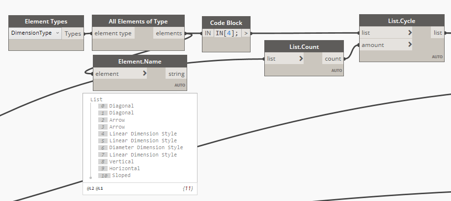
Once we have our References, we will need a Dimension Type. That’s basically the object that determines, the size of text, offset for tick marks etc. The only thing to pay attention to here, is to make sure that we select a Linear Dimension Type. Also important is that you would invariable have more than just one Linear Dimension Type available in the model. Some might be internal types for things like temporary dimensions that Revit displays when we draw things. I think they would work for us, but I am not sure I can recommend using them.
The final piece of the puzzle is creating the Dimension itself.

I missed one important thing. That’s the location line for the Dimension. The last “click” in our process of creating a Dimension String, that sets the location/offset. In order to calculate one, that’s always offset in the View’s UP direction, I created a little utility node. Here’s the code:
Now, this little utility always tries to offset the line in view’s up direction. Up is basically up direction on the screen. That’s problematic when we have a wall that’s not horizontal on a screen, but the assumption here is that we will rotate all walls, into horizontal location in the next post. For now, this is a little limited, as it would do the job well, for Walls created in screen’s horizontal direction only. Sorry.
Anyways, I hope this is helpful. I was able to create a set of dimensions like this:

Also, some of the nodes created for this post, will surely come handy with other tasks that you might be dealing with. Again, all files are available for download for my Patreon supporters, and everyone else will have to re-create this workflow from images. I personally prefer to do that, than just download something. The thing with following a post like that and re-creating it from images, is that you get to really understand the script that you are building. I think that’s valuable.
Here’s the full script so far:


Will you be finishing this series? I am very interested to see how you handled making the elevations.
As a follow up question, do you think this dimension system could be adapted to work in elevation instead of plan?
No idea. I have been super slammed with work recently, and wasn’t able to put some time aside for blogging. I have been asking folks to sign up and support archi-lab.net blog here: https://www.patreon.com/archilab That way I will be able to put aside some time every month, and actually finish these series up like I wanted to. Cheers!